

Yes we do have a retard able ignition that will work on our Saturns. First I
would like to recognize Sean for
discovering this and letting me pick his brain on how to get things up and
working. I will be adding pictures to these instructions as I have them ready.
MAKE SURE YOU READ ALL OF THESE INSTRUCTIONS BEFORE YOU START ANYTHING.
I have since removed and sold the MSD system but this guide is here for
others.
These are the parts you will need:
- (2) MSD Part Number 8870
(This is the insert that redirects the signal from the ignition module to the
coils so that the MSD Ignition can tap into the signal)
- MSD Part Number 6211 or
62111 (This is the ignition itself, the DIS-2. The 6211 is the standard
ignition and the 62111 is the High Output version. If you are going to be
doing any heavy racing I would strongly suggest the HO model. And, at only $10
difference at Summit Racing why
not?)
- Upgraded Spark Plug Wires. I already had Magnecor 8.5mm wires but another
Saturn owner installed the MSD with his stock wires and they got burned in
less than 24 hours. You WILL need upgraded wires and my Magnecor wires have
never failed me.
- (4) 6mm (1.0 thread pitch) X 65mm Screws - For models without the spark
plug boot retainer
(2) 6mm (1.0 thread pitch) X 65mm AND (2) 6mm (1.0 thread pitch) X 95mm -
For models WITH the spark plug boot retainer (HARD TO FIND!! If you can live
without the retainers then just get the 4 65mm screws)
(These are for bolting the coil with the 8870's back on to the ignition
module. The screws that MSD provides are too thin, 4mm diameter I think, and
will not work for us.)
| Stock Bolts vs. MSD
Supplied |
End to End
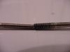 |
Side by Side
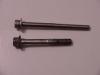 |
- Wire crimpers (for crimping the butt connectors from the 8870s' leads to
the 'umbilical' of the 6211(1).)
- Volt Meter (Self explanatory)
- Momentary Push On Button Switch (For 2-step Rev Limit. When the button is
pushed in the circuit is closed. When the button is out the circuit is open)
UPDATE: If you have a manual transaxle you can tie the 2-step into the clutch
and there is no need for the Momentary Switch.
- Single Pole, Single Throw Switch (For Starter Kill)
- Spare wire for connecting Switches to ground
- Patience and GOOD LIGHT. (You will be patching 8 pairs of wires with
colors that sometimes run together after you have been looking at them for a
while. DO NOT TRY TO RUSH THIS)
Now the instructions.
- Mark and unplug the 4 spark plug wires from the coils and set aside.
- Remove the bolts from one of the coils (2 total) and remove the coil from
the ignition module. You will have to put a little bit of force behind it
because the connections themselves are tight AND there are plastic clips
holding the coils to the ignition module as well.
- Turn the key to the ON position and use your volt meter to verify which
one of the terminals is positive. On the Saturns that I have seen and heard
about the inside 2 terminals are the positive ones. Just check to make sure
your Saturn is not different. If your positive terminals are not the inside 2
then stop reading because the wiring diagram is specific to those 2 being the
positive terminals.
- Take one of your 8870's and clip/file off the 2 numbs next to the male
terminals of the 8870. Connect the coil to the 8870 and make sure that the
coil fits in with a little bit of resistance to show that the terminals of the
8870 ARE making SOLID contact with the female terminals of the coil. If the
coil is not seating tightly (as was the case with 1 of Sean's modules) then
you will need to file down more of the 8870 to allow the male terminals to
extend more.
- Fit the 8870/Coil assembly on to the interface module and screw in with
your new 6mmX65mm bolts. With the bolts I got the head was too large and I
could not fit my socket around the head and fit in between the terminals on
the coil. What I did to resolve this was carve a slot in the head of the bolt
with my Dremel and screw it in with a flat head screw driver.
- Repeat steps 2-5 for the other coil. Again check to make sure the inside
terminal is the positive terminal.
-
The wiring below is read from the left white wire on the
left interface all the way through to the right side white wire on the right
interface.
| |
Left Coil |
Right Coil |
| Position |
1 |
2 |
3 |
4 |
1 |
2 |
3 |
4 |
| Wire on Interface |
White |
Black |
Black |
White |
White |
Black |
Black |
White |
| Wire on DIS-2 Umbilical |
Brown/White |
White |
Red |
Brown/Orange |
Brown/Orange |
Red |
Green |
Brown/Green |
If your interface (8870) has the 4 wires in a square configuration use the
table below to identify their position for the chart above.
|
Layout of Interface Wiring |
White
1 | White
4 |
Black
2 | Black
3 |
- Using your crimper, crimp the butt connectors connecting the wire on the
interface with the corresponding wire on the DIS-2 Umbilical. Make sure your
connections are TIGHT.
- Using a lighter or other flame, heat up the plastic butt connectors to
shrink the plastic and make the connection water tight. Be sure not to melt
the plastic insulation of the wire itself and expose the wire.
- With the supplied loop back plug installed to the end of the umbilical try
to start the engine. If it starts and runs then continue. If not, double check
your connections.
- Route the umbilical to the place where you will mount your DIS-2 to make
sure it will fit. According to MSD the material that the DIS-2 is manufactured
out of the DIS-2 can be mounted in the engine compartment with out damaging
the unit. I will be mounting mine under the dash in the drivers compartment.
- Mount your switches. Remember the Push Button/2-Step need to be accessible
while you are staged without occupying one of your hands (close or on the
shifter would be wise) UPDATE: If you want to tap into the clutch switch then
skip the mounting of the Push Button switch. The starter kill switch should be
hidden as this is a theft prevention switch.
- Connect 1 wire from your spare wire from 1 terminal of your switch (2-step
or starter kill) to a good ground.
- Repeat for the other switch.
- Mount your DIS-2
- Connect the light blue wire from the DIS-2 to the remaining terminal of
the push button/2-step switch. If you want to tap into the Clutch then connect
the blue wire from the DIS-2 to the YELLOW wire coming off the push switch
that gets pushed in when you press the clutch all the way in. See picture
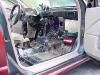
below of the Umbilical Route under the pedals for visual.
- Connect the brown wire from the DIS-2 to the remaining terminal of the
SPST/Starter kill switch.
- Connect the Heavy Red lead from the DIS-2 (NOT the umbilical) to a power
source that is always on (Battery)
- Connect the Heavy Black lead from the DIS-2 to a GOOD GROUND.
- Use the following table to set the switches on the DIS-2. A "O" in the
position means the switch needs to be in that position. A Location without a
setting is up to you on what you want it to be (Rev Limit, Timing Retard)
| |
SW1 |
SW2 |
SW3 |
| |
1 |
2 |
3 |
4 |
5 |
6 |
7 |
8 |
1 |
2 |
3 |
4 |
5 |
6 |
7 |
8 |
1 |
2 |
3 |
4 |
5 |
6 |
7 |
8 |
| On |
|
|
|
O |
|
|
|
|
|
|
|
|
|
|
|
|
|
|
|
|
|
|
|
|
| Off |
O |
O |
O |
|
O |
|
|
|
|
|
|
|
|
|
|
|
|
|
|
O |
|
|
|
|
- Plug the Umbilical to the DIS-2, Cross your fingers, and start the engine.
The car should start and idle the same as before. You will hear a clicking
from the DIS-2 along with the Red LED on the DIS-2 Pulsing.
- You can now adjust your switches to what you want. Remember, when you
change the switch settings the engine has to be started and turned off twice
before the new settings will be used. On the 3rd start after switches were
changed the new settings will be in effect.
- Be safe and Have fun
Here are some of the pictures I have taken.
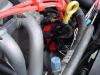
Before
 |
Coil Assy from
Side
 |
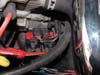
Coil Assy from
Top
 |
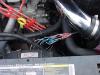
Wires coming
off Coil
 |
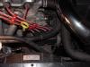
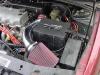
Umbilical Route
in engine bay
 |
Umbilical Route
and Clutch Push
Button
 |
| |
DIS-2 Install
|
|
If you have anything you would like to add to this page please feel free to
write me.


